FLOW LIMITER
99
Safety Valves
28059-500 SERIES
FLOW LIMITER
INLINE •
MALE NPTF TO MALE ORS
Description
AN IN-LINE FLOW LIMITER WITH A MALE NPTF INLET AND A MALE ORS OUTLET THAT PREVENTS FREE FALL IN THE EVENT OF A LINE FAILURE, BUT ALLOWS A METERED FLOW AFTER CLOSING.
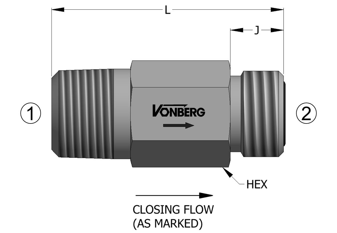
Product Rendering

Schematic

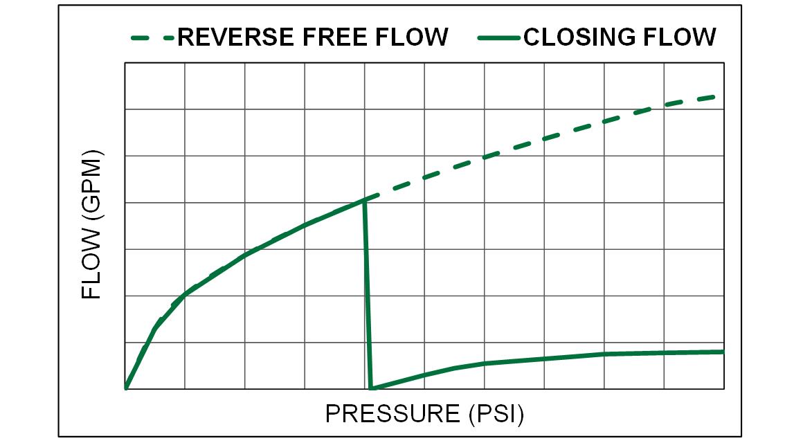
Typical Performance

Operation
- BLEED RATE AFTER CLOSING IS 2.0 - 3.0 GPM AT 3000 PSI.
- FLOW FROM (2) TO (1) PASSES THROUGH THE CONTROLLING ORIFICE BUT IS UNCONTROLLED.
- A FLOW BELOW THE SPECIFIED LIMIT IS ALLOWED FROM (1) TO (2).
- FLOW ABOVE THE SPECIFIED LIMIT IS ASSUMED TO BE A LINE FAILURE AND IS LIMITED.
Features
- NON-STANDARD BLEED FLOW RATES ARE AVAILABLE UPON REQUEST.
- FAIL SAFE DESIGN.
- STEEL COMPONENTS.
- RAPID RESPONSE.
Specifications
| CLOSING FLOW TOLERANCE |
+15% / -0% |
| OPERATING PRESSURE |
3500 PSI |
| REOPENING DIFFERENTIAL |
50 PSI |
| TEMPERATURE RANGE |
250° F TO -40° F |
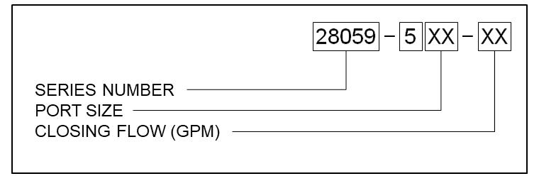
Ordering Information

| 28059-502 | 1/4-18 NPTF | -04 ORS - 9/16-18 | 0.1 TO 4.0 GPM | 2.30 | 0.625 | 0.389 |
28059-503 | 3/8-18 NPTF | -06 ORS - 11/16-16 | 0.5 TO 10.0 GPM | 2.10 | 0.750 | 0.441 | 28059-504 | 1/2-14 NPTF | -08 ORS - 13/16-16 | 1.0 TO 25.0 GPM | 2.34 | 0.875 | 0.504 | 28059-506 | 3/4-14 NPTF | -12 ORS - 1 3/16-12 | 2.0 TO 40.0 GPM | 2.75 | 1.250 | 0.670 | 28059-508 | 1-11 1/2 NPTF | -16 ORS - 1 7/16-12 | 2.0 TO 50.0 GPM | 3.25 | 1.375 | 0.689 | 28059-512 | 1 1/2-11 1/2 NPTF | -24 ORS - 2-12 | 5.0 TO 80.0 GPM | 4.85 | 2.125 | 0.689 |
28059-502View More
1/4-18 NPTF
-04 ORS - 9/16-18
0.1 TO 4.0 GPM
2.30
0.625
0.389
28059-503View More
3/8-18 NPTF
-06 ORS - 11/16-16
0.5 TO 10.0 GPM
2.10
0.750
0.441
28059-504View More
1/2-14 NPTF
-08 ORS - 13/16-16
1.0 TO 25.0 GPM
2.34
0.875
0.504
28059-506View More
3/4-14 NPTF
-12 ORS - 1 3/16-12
2.0 TO 40.0 GPM
2.75
1.250
0.670
28059-508View More
1-11 1/2 NPTF
-16 ORS - 1 7/16-12
2.0 TO 50.0 GPM
3.25
1.375
0.689
28059-512View More
1 1/2-11 1/2 NPTF
-24 ORS - 2-12
5.0 TO 80.0 GPM
4.85
2.125
0.689
Page last updated: 2/25/19, 7:03 PM
This document, as well as all catalogs, price lists and information provided by Vonberg Valve, Inc., is intended to provide product information for further consideration by users having substantial technical expertise due to the variety of operating conditions and applications for these valves, the user, through its own analysis, testing and evaluation, is solely responsible for making the final selection of the products and ensuring that all safety, warning and performance requirements of the application or use are met.
The valves described herein, including without limitation, all component features, specifications, designs, pricing and availability, are subject to change at any time at the sole discretion of vonberg valve, inc. without prior notification.


