COUNTERBALANCE VALVE
346
Pressure Controls
57T SERIES
COUNTERBALANCE VALVE
CARTRIDGE •
T SERIES CAVITY, EXTERNALLY VENTED PORT 4
Description
A CARTRIDGE STYLE , FOUR PORT, PILOT TO OPEN COUNTERBALANCE VALVE WITH A VENTED SPRING CHAMBER TO A FOURTH PORT AND FREE REVERSE FLOW CHECK, INTENDED FOR MOTION CONTROL AND OVER-CENTER LOAD HOLDING APPLICATIONS.
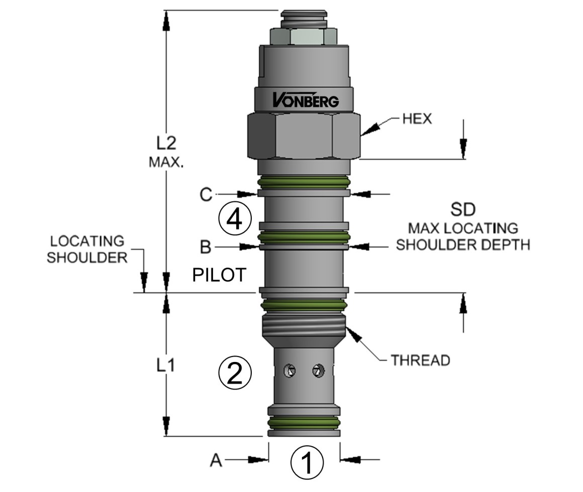
Product Rendering

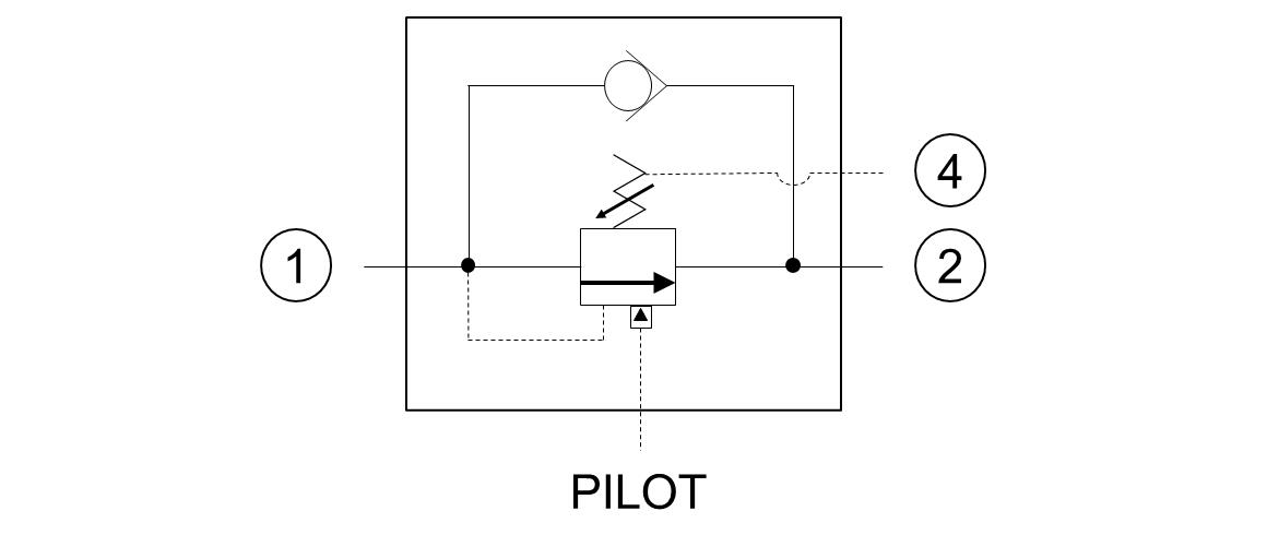
Schematic

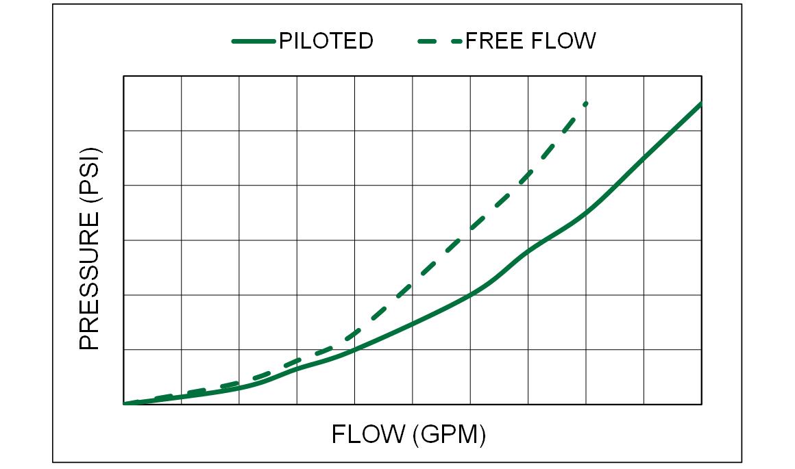
Typical Performance

Operation
- BACK PRESSURE AT PORT (2) DOES NOT AFFECT RELIEF SETTING.
- FLOW FROM (1) TO (2) IS BLOCKED UNTIL A PILOT PRESSURE INVERSELY PROPORTIONAL TO THE LOAD PRESSURE IS APPLIED TO THE PILOT PORT.
- FLOW FROM (2) TO (1) IS ALLOWED WITH A STANDARD CRACK PRESSURE OF 25 PSI.
- FLOW FROM (1) TO (2) IS BLOCKED UNTIL THE RELIEF PRESSURE SETTING HAS BEEN EXCEEDED.
- SPRING CHAMBER VENTED TO FOURTH PORT.
Features
- LOW RELIEF HYSTERISIS.
- SEALED PILOT PISTON, LOW INTERNAL LEAKAGE.
- QUIET, STABLE OPERATION.
- ADJUSTABLE WITH LOCKING NUT.
- CLOCKWISE ADJUSTMENT TO INCREASE RELIEF.
- PILOT RATIOS UP TO 10:1 AVAILABLE (HIGHER PILOT RATIOS MAY REDUCE FLOW CAPACITY).
Specifications
| INTERNAL LEAKAGE |
5 DROPS/MIN. MAX. |
| OPERATING PRESSURE |
5000 PSI |
| RELIEF SETTING RANGE |
+/- 10% |
| STANDARD CRACK PRESSURE |
25 PSI |
| TEMPERATURE RANGE |
250°F TO -40°F |
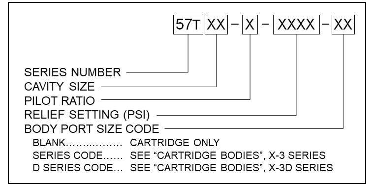
Ordering Information

| 57T21 | M20 X 1.5 | 15.0 GPM | T-21A | 1.38 | 2.81 | 0.938 | 0.683/0.685 | 0.55/0.57 | 0.86/0.85 | 1.27" | 30 FT-LBS |
57T22 | 1-14 | 30.0 GPM | T-22A | 1.38 | 3.10 | 1.125 | 0.871/0.873 | 1.074/1.076 | 1.104/1.106 | 1.72" | 40 FT-LBS | 57T23 | M36 X 2 | 60.0 GPM | T-23A | 1.81 | 4.60 | 1.625 | 1.246/1.247 | 1.558/1.559 | 1.589/1.590 | 1.72" | 95 FT-LBS |
57T21View More
M20 X 1.5
15.0 GPM
T-21A
1.38
2.81
0.938
0.683/0.685
0.55/0.57
0.86/0.85
1.27"
30 FT-LBS
57T22View More
1-14
30.0 GPM
T-22A
1.38
3.10
1.125
0.871/0.873
1.074/1.076
1.104/1.106
1.72"
40 FT-LBS
57T23View More
M36 X 2
60.0 GPM
T-23A
1.81
4.60
1.625
1.246/1.247
1.558/1.559
1.589/1.590
1.72"
95 FT-LBS
Page last updated: 8/1/22, 6:21 PM
This document, as well as all catalogs, price lists and information provided by Vonberg Valve, Inc., is intended to provide product information for further consideration by users having substantial technical expertise due to the variety of operating conditions and applications for these valves, the user, through its own analysis, testing and evaluation, is solely responsible for making the final selection of the products and ensuring that all safety, warning and performance requirements of the application or use are met.
The valves described herein, including without limitation, all component features, specifications, designs, pricing and availability, are subject to change at any time at the sole discretion of vonberg valve, inc. without prior notification.


